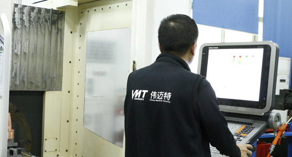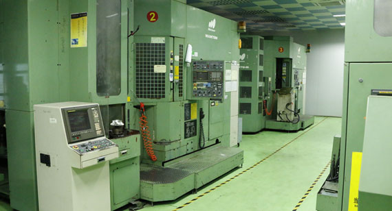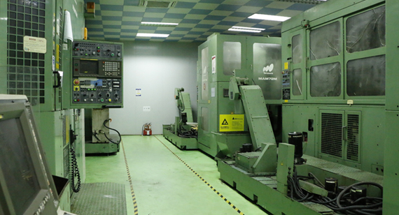
16 years one-stop China custom CNC machining parts factory

Hey there I’m VMT Sam!
With 25 years of CNC machining experience we are committed to helping clients overcome 10000 complex part-processing challenges all to contribute to a better life through intelligent manufacturing. Contact us now
 455 |
Published by VMT at Aug 11 2026 | Reading Time:About 6 minutes
455 |
Published by VMT at Aug 11 2026 | Reading Time:About 6 minutes


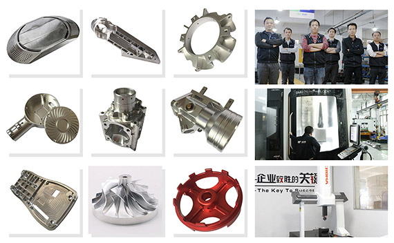
When a part contains angled holes, deep cavities, complex curves, or tightly related features on multiple faces, repeated CNC setups can increase alignment error, fixture cost, and production time. 5-axis CNC machining helps reduce these risks by giving the cutting tool greater access to the part and allowing more features to be machined in fewer setups.
5-axis CNC machining is a subtractive manufacturing process using three linear axes—X, Y, and Z—plus two rotary axes. This allows the cutting tool to approach a part from multiple directions, making it suitable for complex geometries, multi-face features, deep cavities, curved surfaces, and precision components that would otherwise require several machining setups.
Understanding the technology is only the first step. The more important question is whether your part actually needs 5-axis machining—or whether 3-axis or 3+2 machining could achieve the required result at a lower cost.
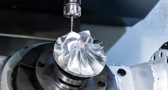
5-axis CNC machining is a computer-controlled machining process in which the cutting tool and workpiece can be positioned using five controlled axes.
A conventional 3-axis CNC milling machine operates along the X, Y, and Z linear axes. A 5-axis machine adds two rotary movements, allowing the cutting tool to approach the workpiece from different angles.
Depending on the machine configuration, the rotary axes may be A, B, or C. The machine normally combines X, Y, and Z with two of these rotary axes.
This additional freedom makes it possible to machine angled features, complex contours, deep cavities, multiple faces, and difficult-to-reach surfaces with fewer repositioning operations. Autodesk similarly defines 5-axis machining as CNC movement across three linear axes plus two rotational axes.
For a production buyer, however, “five axes” should not automatically mean “better.” The correct machining method depends on your geometry, tolerance relationships, surface requirements, quantity, and cost target.
If your drawing already contains complex multi-angle features, VMT's 5-axis CNC machining services can be used to evaluate whether full simultaneous 5-axis machining, 3+2 machining, or a simpler machining strategy is the better choice.
The five axes describe the directions in which the machine can control the position and orientation of the cutting tool relative to the workpiece.
| Axis | Movement |
| X | Linear movement from left to right |
| Y | Linear movement from front to back |
| Z | Linear movement up and down |
| A | Rotation around the X-axis |
| B | Rotation around the Y-axis |
| C | Rotation around the Z-axis |
A 5-axis CNC machine normally uses X, Y, and Z together with two rotary axes.
The exact combination depends on the machine design.
For example, one machine may rotate the table, another may tilt the spindle head, while another combines head movement with table rotation. This is why two different 5-axis machining centers can produce similar parts while using very different machine kinematics.
Tip: Do not specify “5-axis machining required” on a drawing unless the machining method is truly part of your engineering requirement. In many projects, specifying functional dimensions and tolerances gives the manufacturer more freedom to choose a lower-cost process.
The process normally starts with your 3D CAD model and 2D manufacturing drawing.
The manufacturer first reviews the geometry, tolerances, datums, material, surface finish, and functional relationships. The goal is to determine how the part should be located, which surfaces must remain related to the same datum, and whether 3-axis, 3+2, or simultaneous 5-axis machining is necessary.
A typical workflow includes:
Five-axis capability becomes particularly valuable when changing the tool orientation allows a shorter cutter to reach a difficult feature or several sides of the part can be completed without repeatedly removing and reclamping the workpiece.
Siemens and Haas both describe reduced setups as one of the practical advantages of multi-axis and 5-axis machining.
However, fewer setups do not mean that every part is literally completed in one clamping. Some parts still require an additional operation for the bottom surface, soft jaws, secondary drilling, finishing, or inspection.
Two machining strategies are especially important when evaluating a custom part:
3+2 Axis CNC Machining
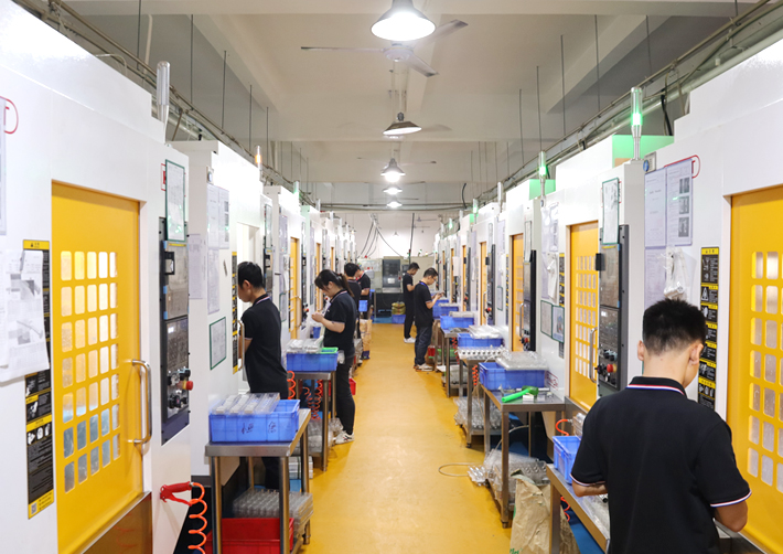
3+2 axis machining is also called positional or indexed 5-axis machining.
The machine uses the two rotary axes to position the workpiece or tool at a required angle. Once the angle is established, cutting is mainly performed with the X, Y, and Z linear axes.
The rotary axes therefore position the part between cutting operations rather than continuously changing orientation during every cut.
3+2 machining can be an excellent solution for:
It often provides many of the setup-reduction benefits of a 5-axis machine without the programming complexity of fully simultaneous machining.
Simultaneous 5-Axis CNC Machining
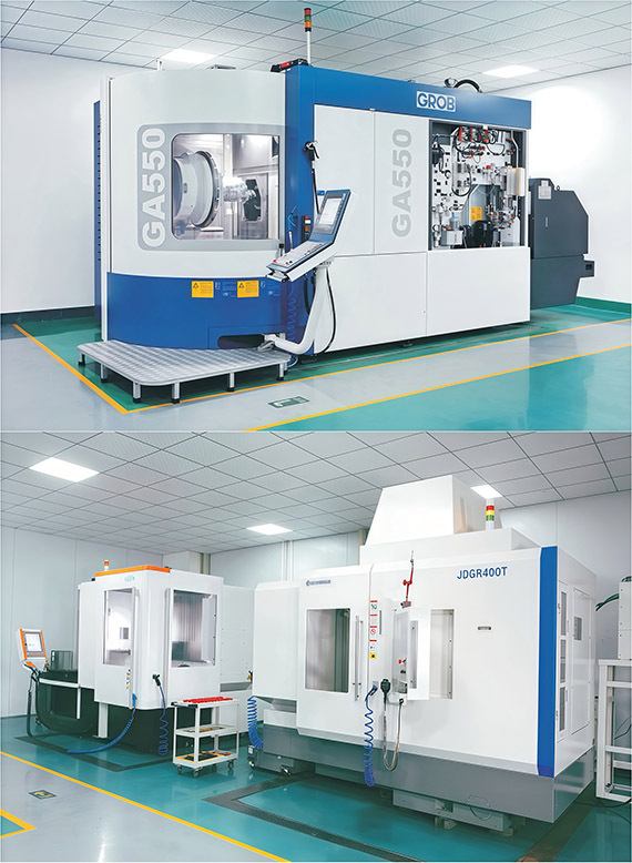
In simultaneous 5-axis machining, the linear and rotary axes can move together while material is being removed.
This allows the tool orientation to continuously change relative to the workpiece.
It is especially useful for:
Haas distinguishes between indexed 5-sided machining and simultaneous 5-axis contouring in the same way.
Tip: A complex-looking part does not automatically require simultaneous 5-axis machining. If the critical features are mainly planar but located at several angles, 3+2 machining may provide a more economical solution.
The best machining strategy is not determined by the number of axes alone.
| Factor | 3-Axis | 3+2 Axis | Simultaneous 5-Axis |
| Linear cutting axes | X/Y/Z | X/Y/Z | X/Y/Z |
| Rotary positioning | No | Yes | Yes |
| Rotary movement during cutting | No | Usually fixed during cutting | Yes |
| Multi-face machining | Requires more setups | Excellent | Excellent |
| Angled planar features | More difficult | Excellent | Excellent |
| Complex freeform surfaces | Limited | Limited to indexed orientations | Excellent |
| Programming complexity | Lower | Medium | Higher |
| Typical machining cost | Lower | Medium | Higher |
| Best use | Simple prismatic parts | Multi-angle features | Continuously changing complex surfaces |
If your main question is how all three-, four-, and five-axis processes compare, the dedicated 3-axis, 4-axis, and 5-axis CNC machining guide should provide the deeper comparison rather than duplicating the same topic here.
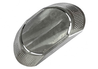
You should consider 5-axis machining when the additional axis movement solves a real manufacturing problem.
Multiple Critical Features on Different Faces
Imagine a housing containing a precision bore on one face, mounting holes on another, an angled connector interface, and a sealing surface on a third side.
Producing all of these features through several independent setups can introduce additional datum-transfer and reclamping risk.
A multi-axis strategy may allow more of these features to remain related within the same machining setup.
Complex Curved Surfaces
Freeform surfaces can require the cutting tool to maintain a changing orientation relative to the surface.
Simultaneous 5-axis machining is particularly valuable when tool orientation must vary continuously.
Deep Cavities
A long tool extending deep into a cavity can become less rigid and more susceptible to vibration or deflection.
Tilting the workpiece or tool can sometimes improve access and allow a shorter cutting tool.
Compound Angles
Parts containing holes, pockets, slots, or surfaces at several non-standard angles may require multiple fixtures on a conventional machine.
5-axis positioning can simplify these operations.
Tight Feature-to-Feature Relationships
When the relative position between features is more important than the individual dimension of each feature, reducing re-fixturing can help control the machining process.
Using the most advanced machine is not always the lowest-risk or lowest-cost solution.
A 3-axis machine may be more economical when your component mainly consists of:
Likewise, a part dominated by cylindrical geometry may be more efficiently produced using CNC turning or turn-mill machining.
The question therefore should not be:
“Can this part be made on a 5-axis machine?”
The better question is:
“Which machining process provides the required function, tolerance, surface quality, and repeatability at the lowest total manufacturing risk?”
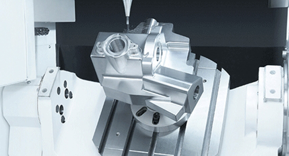
Fewer Machining Setups
One of the most valuable benefits is reducing the number of times a workpiece needs to be manually repositioned.
Every additional setup creates another opportunity for datum transfer, fixture variation, and alignment error.
Better Access to Complex Geometry
Rotating or tilting the workpiece allows the tool to reach surfaces that may be difficult to machine from a fixed vertical direction.
This is particularly useful for angled holes, undercut-adjacent surfaces, side features, complex cavities, and curved components.
Shorter and More Rigid Cutting Tools
Changing the tool orientation may allow the spindle to move closer to the cutting area.
A shorter tool generally provides better rigidity than a long tool reaching the same feature from a fixed direction.
Better Control of Complex Surface Finish
For curved surfaces, controlling the cutting direction and contact between the cutter and surface can improve machining conditions.
The result still depends on tool selection, stepover, feed rate, spindle speed, toolpath strategy, material, machine condition, and finishing requirements.
Reduced Fixture Requirements
Complex multi-sided components can otherwise require several custom fixtures.
Reducing fixture changes can decrease setup effort and simplify process control.
Better Repeatability for Suitable Parts
Once the fixture, program, toolpath, inspection method, and cutting parameters are validated, a multi-axis process can provide a stable route from prototype to repeat production.
5-axis machining does not automatically guarantee perfect accuracy.
In fact, the increased freedom of motion creates new process risks.
More Complex Programming
Toolpath planning becomes more demanding because the programmer must consider tool orientation, rotary movement, fixture clearance, spindle clearance, and machine travel.
Collision Risk
The tool, holder, spindle, fixture, table, and workpiece can move relative to one another.
CAM simulation and process review therefore become especially important.
Rotary-Axis Accuracy
The accuracy of a complex part depends not only on X, Y, and Z movement but also on rotary-axis calibration and machine kinematics.
Thin-Wall Deformation
Five-axis access does not eliminate material deformation.
Thin walls can still move when residual stress is released or when clamping and cutting forces are poorly controlled.
Chatter and Tool Deflection
Deep cavities and long-reach tools can still create vibration.
Tool orientation must be combined with appropriate cutter length, engagement, cutting parameters, and machining sequence.
Surface Blending Marks
Poorly planned finishing strategies can leave visible transitions between machining regions.
This is especially important for cosmetic components, molds, optical equipment parts, and products that will later be polished or anodized.
Higher Cost When the Process Is Unnecessary
A 5-axis machine generally involves more complex equipment, programming, setup, and process planning.
Therefore, using it for a simple part can increase cost without providing meaningful manufacturing value.
The quality of a 5-axis part depends on much more than the machine itself.
At VMT, the machining plan begins with an engineering review of your CAD model and manufacturing drawing. The team can evaluate material, dimensional requirements, surface finishing, part geometry, and manufacturing feasibility before machining begins. VMT's existing quality system also includes in-process inspection and CMM measurement for complex precision components.
For a complex 5-axis project, important controls may include:
DFM and Tolerance Review
Not every dimension should receive the same tolerance.
Critical assembly interfaces, sealing areas, bearings, hole positions, mating surfaces, and datum relationships should be identified before the toolpath is finalized.
Fixture Optimization
The fixture must provide enough rigidity without creating unnecessary distortion or blocking tool access.
Datum Strategy
Critical features should be related to suitable datums so that inspection represents the actual functional requirement of the part.
Machining Sequence Control
Roughing, stress release, semi-finishing, and finishing may need to be separated for parts prone to deformation.
Toolpath Optimization
Tool orientation, cutting direction, engagement, stepover, and cutter length can affect accuracy and surface condition.
In-Process Inspection
Critical features can be checked before the part proceeds to later machining or finishing operations.
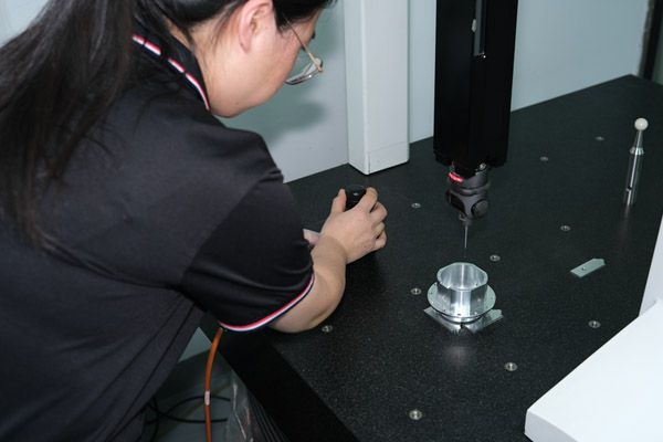
Final CMM Inspection
For complex geometry and closely related positional features, CMM inspection provides a practical way to verify dimensional relationships against the drawing.
5-axis CNC machining can be used with many metals and engineering plastics. VMT's existing machining capability includes aluminum, stainless steel, steel, titanium, copper alloys, and engineering plastics.
| Material | Common Reason for 5-Axis Machining | Main Manufacturing Concern |
| Aluminum | Complex lightweight housings, brackets, prototypes | Burrs, thin-wall deformation, cosmetic finish |
| Stainless Steel | Medical, fluid-control and industrial components | Cutting heat, tool wear, burr control |
| Titanium | Aerospace and high-performance components | Heat concentration, tool wear, cutting stability |
| Alloy/Tool Steel | Molds and mechanical parts | Hardness, tool wear, machining time |
| Brass/Copper | Precision interfaces and electrical components | Burrs, surface damage, material behavior |
| Engineering Plastics | Lightweight precision components | Clamping deformation, thermal expansion |
Note: Material selection should be based on the final operating environment rather than machining convenience alone.
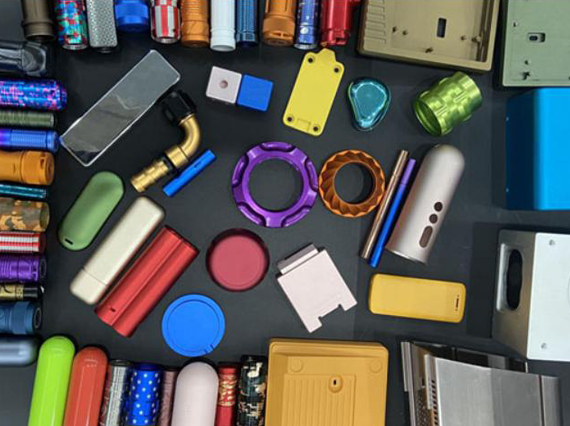
The machining strategy should also consider what happens after the part leaves the CNC machine.
Depending on material and application, suitable surface finishes may include:
VMT currently supports multiple post-machining finishing processes as part of its custom CNC workflow.
Finishing requirements should ideally be defined before machining.
For example, cosmetic surfaces may require control of cutter marks before bead blasting or anodizing, while critical fits, threads, grounding surfaces, sealing faces, or datum areas may need masking or dimensional allowance.
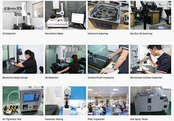
Inspection should follow the function of the drawing.
Simple dimensions may be checked with calipers, micrometers, height gauges, pin gauges, thread gauges, or other dedicated tools.
Complex geometric relationships are better suited to coordinate measuring equipment.
For example, a 5-axis component may require verification of:
VMT's quality process includes first-article, in-process and final inspection, with CMM used for complex precision parts where appropriate.
Tip: Do not assign ±0.01 mm to an entire drawing simply because a supplier owns a 5-axis machine. Apply tight tolerances only to features that require them. This normally makes production easier to control and avoids unnecessary machining cost.
5-axis machining is especially valuable when a component combines complex geometry with demanding dimensional relationships.
Typical applications include:
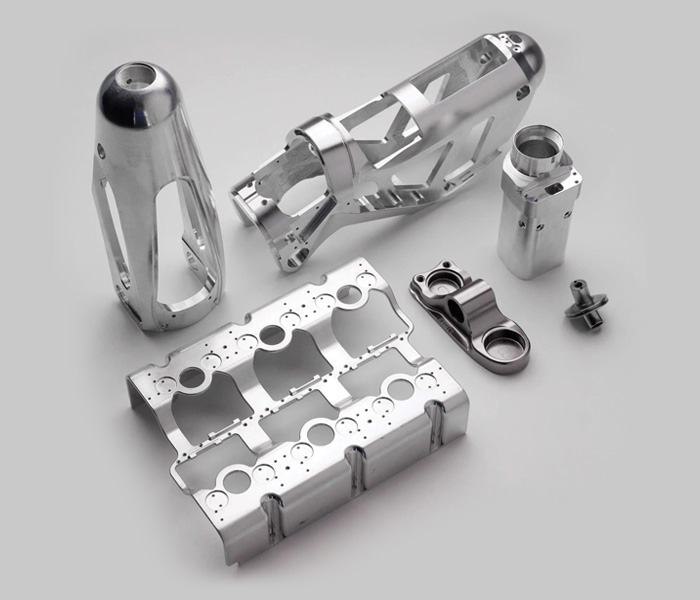
Examples include structural components, blade-type geometry, impellers, mounts, brackets, and complex lightweight parts.
Medical and Laboratory Equipment
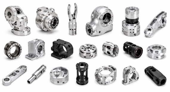
Multi-angle instrument components, robotic joints, surgical equipment parts, and precision fixtures can require complex machining and detailed inspection.
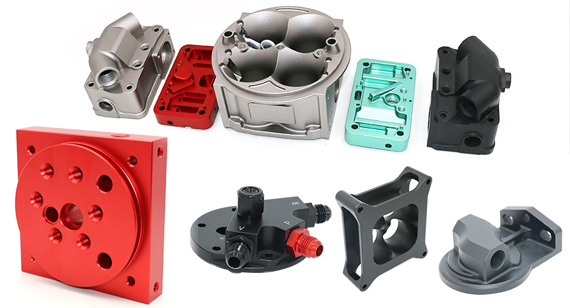
Prototype engine components, transmission components, suspension parts, motorsport components, housings, and development fixtures may benefit from multi-axis machining.
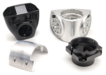
Robot joints, sensor housings, end-effector components, precision mounts, and structural interfaces frequently contain features on multiple orientations.
Electronics and Optical Equipment
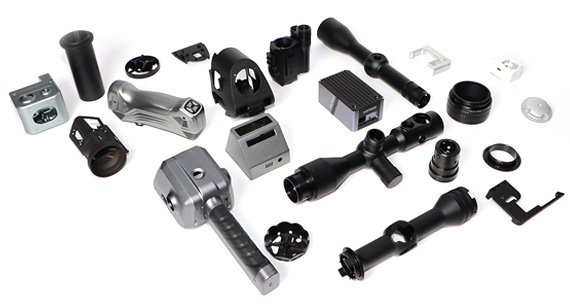
Complex housings, camera parts, optical mounts, heat-management components, frames, and precision enclosures may combine functional interfaces with cosmetic surfaces.
Mold and Tooling Components
Complex contoured surfaces and angled geometry can make multi-axis machining useful for mold inserts, dies, and tooling.
Project Background
Consider an aluminum equipment housing containing precision mounting surfaces, angled connector ports, internal pockets, multiple threaded holes, and several critical interfaces located on different sides of the component.
Project Challenge
Producing every feature with separate 3-axis setups would require repeated repositioning of the workpiece.
This creates additional fixture requirements and makes the positional relationship between features more difficult to control.
VMT Machining Approach
The engineering team first reviews the drawing to identify critical datums and functional interfaces.
A multi-axis strategy can then be selected so that as many related features as practical are machined within the same controlled setup.
The process may combine rough machining, 3+2 positioning, localized simultaneous 5-axis toolpaths, in-process inspection, finishing, and final CMM verification.
Result
The value is not simply that “a 5-axis machine was used.”
The real manufacturing benefit comes from reducing unnecessary setups, improving tool access, controlling relationships between critical features, and establishing a repeatable process that can later support production batches.
A stable 5-axis manufacturing process should be developed step by step.
1. Upload 2D and 3D Files
Provide both the CAD model and manufacturing drawing whenever possible.
2. Engineering and DFM Review
Review materials, tolerances, surface requirements, datums, critical interfaces, wall thickness, threads, cavities, and inspection requirements.
3. Choose the Machining Strategy
Determine whether the part requires:
4. Fixture and CAM Development
Plan workholding, tool access, tool lengths, machining sequence, and collision avoidance.
Produce the first part and identify any unexpected deformation, burr, surface, tolerance, or fixture issues.
6. Inspection and Validation
Check functional dimensions and compare the measured result with the drawing.
7. Surface Finishing
Complete anodizing, polishing, passivation, plating, or other required finishing operations.
8. Repeat Production
Once the machining and inspection process is validated, the same controlled manufacturing route can be applied to subsequent batches.
5-axis CNC machining is most valuable when its additional freedom solves a specific manufacturing problem—complex geometry, multiple angled features, difficult tool access, repeated setup risk, or demanding relationships between critical surfaces.
But not every complex-looking part needs full simultaneous 5-axis machining.
A good CNC supplier should first evaluate whether your project is better suited to 3-axis, 3+2, simultaneous 5-axis, turn-mill, or a combination of manufacturing processes.
If you are developing a complex CNC machined part, upload your 2D and 3D drawings to VMT. Our engineering team can review the geometry, tolerances, material, surface requirements, and production quantity, then provide DFM feedback and recommend an appropriate machining strategy.
Request a quote and ask for a 5-axis CNC machining DFM review for your project.
Send your 2D drawing, 3D CAD model, material, quantity, tolerance requirements, surface finish, critical dimensions, and assembly or functional requirements. VMT will review whether 3-axis, 3+2, simultaneous 5-axis, turn-mill, or a combined strategy is the better manufacturing route.
All information and uploaded files are secure and confidential.
1 Tell us what you need
2 Get DFM & quote
3 Approve production
Email: inquiry@vimetal.com.cn
What is the simple definition of 5-axis CNC machining?
5-axis CNC machining uses three linear axes—X, Y, and Z—together with two rotary axes to control the position and orientation of a cutting tool relative to a workpiece.
What are the five axes on a CNC machine?
The three linear axes are X, Y, and Z. Rotary axes are called A, B, and C, representing rotation around X, Y, and Z respectively. A 5-axis machine normally combines XYZ movement with two rotary axes.
Is 3+2 machining the same as simultaneous 5-axis machining?
No. In 3+2 machining, rotary axes mainly position the part or tool before the cutting operation continues. In simultaneous machining, rotary and linear axes can move together during cutting. Haas also distinguishes these two operating modes.
Is 5-axis machining more accurate than 3-axis machining?
Not automatically. Five-axis machining can reduce errors associated with multiple setups, but final accuracy also depends on machine calibration, fixturing, datum strategy, tool condition, temperature, cutting parameters, programming, and inspection.
Is 5-axis CNC machining always more expensive?
The machine and programming cost can be higher, but total part cost may be lower when five-axis machining removes several fixtures, reduces setup time, improves tool access, or prevents rework. For simple geometry, 3-axis machining is usually more economical.
What parts are best suited for 5-axis CNC machining?
Parts containing complex curved surfaces, angled features, multi-face machining, difficult tool access, deep cavities, or tight positional relationships between features are strong candidates.
What materials can be 5-axis machined?
Common choices include aluminum, stainless steel, steel, titanium, brass, copper, POM, PEEK, nylon, and other machinable engineering materials. Material behavior must still be considered when selecting tools and cutting conditions.
Can 5-axis machining produce prototypes?
Yes. Multi-axis machining is widely used for functional prototypes and complex development components because it can machine detailed geometry directly from CAD data without dedicated production tooling.
Can the same process be used for production batches?
Yes, provided the fixture, program, cutting conditions, tool-control plan, inspection method, and finishing process are validated for repeatability.
What information should I provide for a 5-axis machining quotation?
Send your 3D model, 2D drawing, material, quantity, tolerance requirements, surface finishing, critical dimensions, and any assembly or functional requirements.


 +86 15099911516




 Read more